Requirements
Agree on aircraft class, sensor set, outputs, power, board size, firmware target, setup route and acceptance criteria. Define what is a mandatory requirement and what can change. Name the reference aircraft and connected parts.
Send your BOM, target market and annual volume. Our team will map compatible parts and documentation.
Upload your BOM ↑Request engineering samples →Send your BOM, target market and annual volume. Our team will map compatible parts and documentation.
Upload your BOM ↑Request engineering samples →Send your BOM, target market and annual volume. Our team will map compatible parts and documentation.
Upload your BOM ↑Request engineering samples →Send your BOM, target market and annual volume. Our team will map compatible parts and documentation.
Upload your BOM ↑Request engineering samples →Send your BOM, target market and annual volume. Our team will map compatible parts and documentation.
Upload your BOM ↑Request engineering samples →Send your BOM, target market and annual volume. Our team will map compatible parts and documentation.
Upload your BOM ↑Request engineering samples →Send your BOM, target market and annual volume. Our team will map compatible parts and documentation.
Upload your BOM ↑Request engineering samples →Send your BOM, target market and annual volume. Our team will map compatible parts and documentation.
Upload your BOM ↑Request engineering samples →OEM and ODM · Flight controller development
A flight controller is a point of connection among sensors, receiver, ESCs, power, firmware and the operator's expectations. Selecting a processor or matching a board outline is only part of the work. A useful development brief describes the aircraft and the conditions in which the controller must operate.
This page sets out the questions to prepare for a custom or adapted flight controller discussion with Sichuan Yuanxin Supply Chain Technology Co., Ltd. The availability of a particular processor, firmware port, test facility or certification must be confirmed for the proposed project.
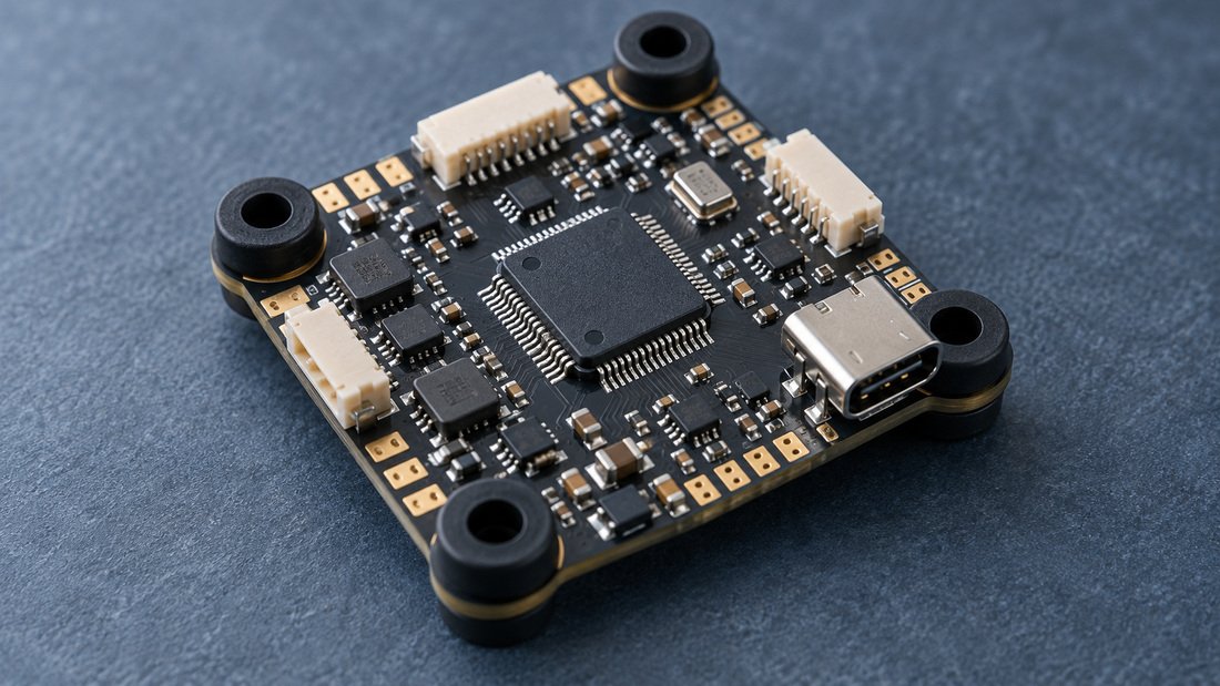
The application comes first
A school drone soccer aircraft, an FPV racing build and a civilian integrated system can all use flight control electronics, but their requirements differ. Describe the airframe, propulsion, radio control link, accessories, operator and safety expectations before selecting a board architecture.
For an FPV build, list the battery range, ESC interface, motor count, receiver type, video system, onboard sensors, mounting pattern and preferred flight firmware. Include physical constraints such as board stack height, USB access and airflow. A controller may appear compatible on a connector chart yet place a port where it cannot be reached after assembly. If the radio link needs telemetry or particular failsafe behavior, state that in the brief.
For a protected drone soccer system, explain the cage or shell, total mass, handling by learners, typical flight session, charging workflow and how a damaged board will be replaced. A school may value clear setup and repeatable maintenance as much as maximum performance. Define what a teacher or club technician should be able to inspect and which procedures require a qualified electronics person.
For a civilian integrator, describe the external subsystems, communications, logging and system level acceptance. If an application has special operational or regulatory requirements, involve the appropriate specialist early. A supplier's claim that a board can run a common firmware does not establish that the complete aircraft is safe or approved for the intended use.
Interface map
Prepare a table that names each power input, regulated output, signal, connector and mating device. Include normal and maximum voltage, expected current, signal level, protocol and pin assignment. Identify which signals are optional and which must remain available for a future accessory. This prevents a familiar connector shell from being mistaken for a compatible pinout. When third-party parts are involved, use their current documentation and record the exact model revision.
Place sensors in the mechanical and electrical context. Orientation, vibration, temperature, electrical noise and mounting all influence what a sensor reports. A design should define the board orientation and calibration expectations rather than merely naming an inertial sensor. If a magnetometer, barometer, GPS or other sensor is part of the proposed system, specify whether it is on the board or external, how it connects and how the firmware will use it.
Think about access during assembly and service. Will the installer reach a USB port, boot control, programming pads or antenna connector once the board is in the airframe? Can a wire be removed without lifting the entire stack? Is there room for the real cable bend radius and fastener head? Check these questions with a representative enclosure or frame, not only a two-dimensional board outline.
Finally, map fault behavior. What should happen if the receiver link drops, power dips, a sensor fails or configuration is incomplete? The exact response depends on application and firmware. Define required behavior as a testable requirement, then validate it on the actual aircraft with appropriate precautions. Do not claim a generic board is fail safe in every installation.
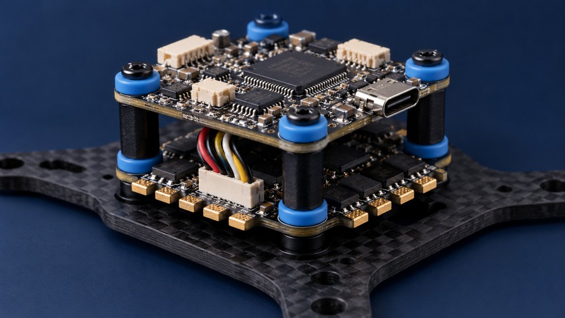
Firmware and validation
Agree on aircraft class, sensor set, outputs, power, board size, firmware target, setup route and acceptance criteria. Define what is a mandatory requirement and what can change. Name the reference aircraft and connected parts.
Choose components and connections with availability, electrical margin and software support in mind. Check whether the firmware can address the proposed pins and devices. A processor's headline speed does not determine compatibility.
Build a traceable board revision. Bring up power and programming first, then sensors and outputs with controlled equipment. Log hand changes and unresolved issues. Do not release a hand modified board as a production specification.
Connect receiver, ESCs and accessories with current pinout documentation. Check calibration, communications, output order and fault behavior. Use a safe test configuration before moving to powered propulsion.
Test the intended configuration in an appropriate controlled environment with qualified personnel. Record firmware, settings, mass, battery and connected equipment. A successful flight under one setup is useful evidence, but it does not replace a broader release plan.
Freeze hardware revision, firmware image, programming and test procedure. Decide how updates will be delivered and identified. Link a later board or firmware change to the aircraft models and customers it affects.
What the brief must settle
Hardware: The controller needs power input, regulation, processor, sensors, outputs, communication ports and mechanical support suited to the build. Specify connector type and orientation; a pinout table should accompany the design. If the ESC supplies voltage or the board distributes power, document the direction and allowed range of each connection. Avoid relying on a colorful wiring photo as the authoritative electrical drawing.
Firmware: Identify the source, license, version, board target, configuration and expected update process. For an adapted design, check whether a supported target can actually map the new hardware. For a new port, define the code, test and maintenance scope. If the buyer needs source access or long-term updates, settle the rights and responsibilities in the contract.
Configuration: Decide which settings are programmed at production and which are set by the integrator or end user. A school fleet may need consistent default setup and a restricted maintenance process. An integrator may need a documented way to apply its own parameters. Record what is stored on the board and how a replacement unit receives the correct configuration.
Diagnostics: A useful controller helps identify the reason for a fault. Agree on indicators, logs, update paths and the information a support team can retrieve. A field report that names board revision, firmware and connected equipment is more actionable than “the drone will not fly.” The design should support a practical troubleshooting workflow within its cost and physical constraints.
Safety and responsibility: The flight controller is one component in an aircraft. Its output depends on power quality, installation, configuration and the rest of the vehicle. An approval should name the tested aircraft and software state. Propulsion, battery, radio link, structural design, software settings, pilot behavior and local rules all matter. The project agreement should state who validates the complete system, who approves flight testing and which documents will accompany the final product. No single component page can confer a blanket safety approval.
Acceptance criteria
Start with an interface checklist: each port's electrical behavior, pin assignment, mechanical accessibility and firmware mapping. Then define sensor behavior and calibration under known conditions. Check output commands and failsafe behavior without exposed propellers before any flight evaluation. Identify the instruments and reference equipment used. A test that cannot be repeated on another board is difficult to use for production release.
Thermal and power conditions need attention. The intended battery, ESC and accessories can create noise or transients that a lab power supply does not reproduce. Evaluate the controller under representative loads and within the proposed enclosure. If a processor or regulator becomes hot, determine whether the issue is design, airflow or operation. Record the limits used in testing instead of publishing an unqualified performance claim.
Mechanical reliability also matters. A board fixed near motors and impacts experiences vibration and handling. Inspect mounting, connector retention and strain relief with the complete harness. A school or club may replace a damaged unit more often than a fixed industrial installation, so service access can be part of acceptance. Any test of durability should state its method, duration and sample size.
Finally, plan production screening. Decide which functions are checked on every unit and which are characterized during development. Maintain a known good reference, verify the test fixture and tie results to the board and firmware revision. The sample approval, production test and aircraft integration check are complementary evidence, not interchangeable certificates.
System handoff
A flight controller development project should end with enough information for the intended assembly team to repeat the build. That may include a pinout, wiring diagram, orientation mark, firmware release, initial configuration, calibration sequence and a checklist for first power-up. The list varies by product and contract. If a third-party integrator will finish the aircraft, ask what it needs to verify before connecting motors or conducting a flight test.
Separate production settings from operator settings. An assembly technician may load firmware and confirm ports; a qualified integrator may tune the aircraft; an instructor may only select a documented operating mode. Write instructions for the person who actually performs each step. A manual that assumes every reader is a firmware engineer can lead to inconsistent fleet configuration in a school or club. A manual that hides all technical detail can leave a professional integrator unable to diagnose a problem.
Plan for replacement. If a controller is damaged, how does a new unit receive the correct firmware and settings? Are cable harnesses keyed and labeled? Can the revision be read without disassembling the entire aircraft? Does the support team know whether a replacement board can be fitted to an older airframe without another check? These questions influence board labeling and documentation early in design.
Think about data collected during support. A useful fault record may contain an order reference, board revision, firmware, flight log, setup changes and environmental conditions. Avoid requesting irrelevant personal information from a school or club. Decide who can access logs and how they are shared. If a controller is linked to an app or network service, include software security and update responsibility in the project scope.
Finally, decide what constitutes a released aircraft configuration. A flight controller can pass its bench test and still need evaluation of the propulsion, radio link, protective structure and pilot procedure together. Record the reference aircraft, battery, propeller and firmware settings used for approval. A later modification should be assessed against that baseline. This disciplined handoff gives purchasers a product they can identify and support rather than a board whose successful prototype depends on undocumented expertise.
Consider how the controller will be installed by someone other than its designer. A connector table can be technically accurate yet difficult to follow if board orientation is unclear. Mark the top view, pin one, input direction and any reversible cable risk. Check the instructions with a technician who did not participate in the prototype. Record where configuration files are stored and how a replacement board is verified. That small handoff test can reveal a documentation gap before a whole fleet relies on it.
Frequently asked questions
Describe the aircraft, power system, sensors, outputs, receiver, ESCs, firmware, dimensions and operating environment. Add a wiring map and reference hardware. State the intended user and any market or safety requirement. A processor name or desired board size alone is not enough to define a workable controller.
It may be possible if the requested change and rights permit it. Identify the current model and revision, the exact difference and the properties that must stay fixed. A connector move may affect routing; a new sensor may require firmware; an antenna related change may require RF review. Ask for an assessment before treating a modified product as an unchanged variant.
Compatibility depends on the receiver's output, power, wiring, firmware and configuration. A generic ELRS label does not prove that a particular receiver can connect to every controller. Compare datasheets and test the exact transmitter, receiver and controller revisions together. Record the approved settings for repeat builds.
That depends on the hardware design, supported board target, licenses and development scope. Ask which firmware version or target is proposed and how it maps sensors, ports and outputs. A prototype that boots a firmware image still needs functional validation. Set expectations for updates and support in the project agreement.
First define the behavior required when a link, sensor or power source fails. Test in controlled conditions with the actual connected equipment and documented firmware settings. Avoid exposed propulsion during early checks. The complete aircraft and operator procedures also influence safety; a board level test alone cannot guarantee an outcome in every flight situation.
The rights depend on the contract and any third-party or open-source components. List the files and source code to be delivered, their format and license, and who may modify or distribute them. A buyer should resolve this before development begins, especially when it intends to maintain a private label product over multiple revisions.
Describe the protective airframe, mass, propulsion, radio and maintenance process. Classroom equipment may need simple setup, clear indicators and a repeatable replacement procedure. Confirm the actual aircraft and instructional environment. The design must still be validated as part of the complete system, and the school must follow its own local safety and operating rules.
It can show that a design concept works under documented conditions. It may contain hand modifications or limited testing and should not be mistaken for a released production item. Record the board and firmware revision, setup and observed results. Determine what further integration, reliability and production checks are needed before volume approval.
No such claim is supported by the supplied documents. Performance depends on aircraft integration, firmware, power, mechanical installation and test conditions. Define the metrics you need and an evaluation method in the brief. A written proposal can state which evidence will be generated and what remains the buyer's system-level responsibility.
Requirements depend on the destination, product role and complete aircraft. Identify the market and any expected radio, EMC or safety evidence. Ask who will arrange evaluation and which documents are included. Do not infer certification from a component name, a generic company statement or a report for another configuration.
Agree on a release identifier, programming file, configuration and verification step. Map that software to the hardware revision and manufacturing lot. If an update changes behavior, decide how it will be approved and communicated. Support staff should be able to identify the installed version when a customer reports a problem.
Provide the board model and revision, firmware, wiring, receiver and ESC models, battery, symptoms, error indicators and steps to reproduce. Include photographs and logs where available. If the controller is part of a custom project, add the order reference and approved configuration. Do not change firmware or rework a suspected failed board before agreeing on the diagnostic path.
Start with a real aircraft
We can discuss the controller, firmware and validation scope once the system and constraints are clear.